VFD bypasses and backups: Which should you use?
Advanced motor protection and consistent energy savings are possible, with true redundancy.
By: Tommy Trullinger, Franklin Control Systems
Learning objectives
1. Learn the differences between traditional solutions to VFD failure and newer methodologies, and the pros and cons of each.
2. Describe a simple selection process to ensure the application is properly protected and backed up in the most economical way.
Originally introduced as an efficient and effective way to reduce energy consumption by allowing motors to be run at different speeds, variable frequency drives (VFDs) have become commonplace in the HVAC industry. While there is no question that VFD technology helps save energy, unfortunately it was somewhat unreliable in the early years. The VFD bypass was introduced to ease concerns around reliability, and it played a significant role in the rise of VFD usage.
A traditional mechanical bypass acts as a backup system to ensure equipment stays operational when or if a VFD fails. A bypass is essentially a motor starter that is built into (around) the VFD to maintain full voltage (across the line) control of the application. The backup allows the application to run at full speed until the problem with the VFD can be addressed.
The bypass, along with the VFD, have become staples of the typical HVAC configuration, and over the years have made their way into almost all consulting engineers’ specifications. The problem is that the majority of specifications today still hang on to the idea that bypasses are always needed. VFDs, like most electronics, have improved dramatically since they were first invented. They’re more reliable now and have extremely low failure rates. They’re also much more compact and economical than in years past.
Recently, VFD manufacturers have developed new and improved bypasses, as well as motor drive packages with full redundant capabilities. Opinions abound about which backup or bypass should be used for various HVAC applications, but there are few guides that provide a definitive answer. To better understand the selection process, it’s important to first look at the pros and cons of the various bypasses and backups available.
Traditional bypass
A traditional bypass consists of a separate motor starter, mechanically interlocked with its
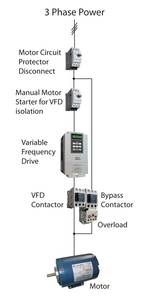
3 Phase Power
companion VFD output contactor in a way that allows only the VFD or the bypass to operate the motor at any given time. Most traditional bypasses default to “manual” operation to engage the bypass. In other words, someone must manually turn on the bypass in the event that the VFD fails. A VFD fault relay can be used to start the bypass automatically based on a VFD fault, but only if the VFD is not damaged. Traditional bypasses are also available in 2- or 3-contactor variations. A 3-contactor bypass (Figure 1) introduces an additional contactor or a VFD isolation switch that disconnects the VFD from power supply. This enables an electrician to completely remove the VFD while the application is running in bypass mode. However, this is not recommended as it sets up the electrician to work in close proximity to high-voltage wiring. A 2-contactor bypass is sufficient for most applications requiring a bypass and does not provide a complete VFD isolation. Also keep in mind that local codes may restrict the actual configuration. Common features of a traditional bypass include:
- Available in 2- or 3-contactor variations
- Disconnect is typically integral
- Hand, Off, Auto switch for VFD and bypass
- VFD/Off/Bypass switch
- Manual bypass standard (auto relay available)
- Thermal overload protection.
The traditional bypass is readily available. Other advantages are that it is inexpensive in comparison to other backups, allows for building automation system (BAS) control, and is extremely reliable. On the downside, a traditional bypass offers no advanced motor protection, needs relays for automatic control, and has no soft start capability. Communication to BAS is limited, communicating status/fault only. All energy savings is lost and consumption is not monitored in bypass mode. Finally, the traditional bypass offers 60Hz operation only…
Electronic bypass (smart bypass)
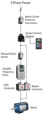
3 Phase Power
The electronic bypass was recently introduced to address a number of concerns with built-in logic and advanced motor protection. This microprocessor-based bypass (Figure 2) offers advanced features such as protection from phase loss, ground fault, over/undervoltage, and over/under power. These protection features go far beyond what a traditional thermal overload provides. Electronic bypasses also typically include a provision for BAS to communicate directly to the bypass in the event of VFD failure. This should be coordinated with BAS software manufacturer. The electronic bypass allows users to select certain conditions in which they want the bypass to start automatically, and incorporates other features that traditionally would only be supported by the VFD (fault logging, delays, etc.). There are also electronic bypasses on the market that integrate full ANSI grade power metering, and BACnet or other communications interfaces to allow for seamless control and communications whether in VFD or bypass mode. Common features of an electronic bypass include:
- Keypad with LED indication
- Communication card
- Advanced motor protection
- Common start/stop terminals
- Fireman’s override
- Bypass fault logging
- Selectable auto bypass
- Power failure modes.
On the positive side, electronic bypasses offer features such as advanced motor protection, BAS communications, logic to assist with troubleshooting, flexible control features, and compact physical size. But these bypasses come at a higher cost. They also lack soft start capabilities and motor speed control in bypass (60Hz only).
Redundant drives
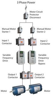
3 Phase Power
Redundant VFDs are the logical next step in control for critical applications (Figure 3). They work on the principle that if one VFD fails, full control and protection are maintained by a second VFD that automatically takes over. Redundant VFDs are not a new concept; the idea has been around for years, but only recently has this concept become cost-effective. With the VFD market becoming more and more competitive, it’s only a matter of time before bypasses fade away as a viable choice, and dual VFD systems become the standard for critical applications. Most VFD manufacturers offer some type of packaged redundant drive systems as part of their custom offering. This means they must be approached on a “job-by-job” basis.
It’s important to understand that these packages require a level of customization because they consist of more than just two VFDs. To maintain true redundancy, extra power and control circuitry must be added. The standby VFD must be isolated from power while the primary VFD is running to ensure both primary and backup VFDs aren’t damaged in the event of a power surge or spike. To isolate the VFDs, mechanically interlocked input contactors should be added. Provisions must also be made to ensure that the backup VFD doesn’t sit for extended periods without being periodically powered up. VFD DC bus capacitors have a shelf life and can degrade without periodic charge cycles. The control system should provide scheduled alternation or charge cycles for standby VFD. The downside of the added power and control components is unfortunately an additional cost.
Pros of redundant VFDs include full redundancy, full control with backup VFD, and advanced motor protection all the time. They provide consistent energy savings. (VFD operation is maintained even when one fails.) However, they are more expensive than traditional and electronic bypasses and have a larger footprint.
Continue reading →


